Introduction
Setting up a metal stamping production line is one of the most impactful investments a manufacturer can make. Whether you're producing automotive brackets, appliance housings, electrical connectors, or structural components, the right production line determines your output quality, cycle time, and long-term profitability.
But a stamping line is far more than just a press machine. It's a fully integrated system — from decoiling and feeding to stamping, transferring, quality inspection, and part collection. Getting the configuration wrong at any stage creates bottlenecks, scrap, and downtime that ripple across the entire operation.
This guide walks you through every stage of setting up a metal stamping production line — from initial planning and press selection to automation, die management, quality systems, and common pitfalls. Whether you're building your first line or upgrading an existing one, this is the reference you need.
Core Components of a Stamping Production Line
A complete metal stamping production line consists of several integrated stations. Each must be matched to the others in speed, capacity, and precision.
1. Coil Handling System
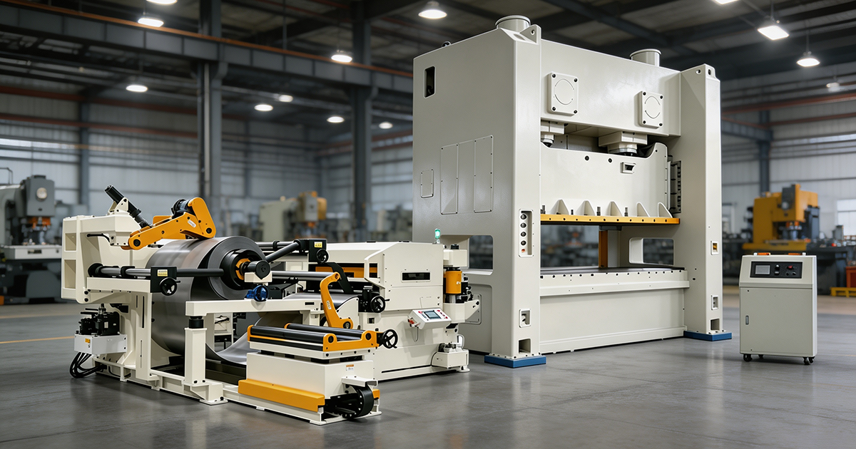
Every stamping line starts with raw material feeding. The coil handling system includes:
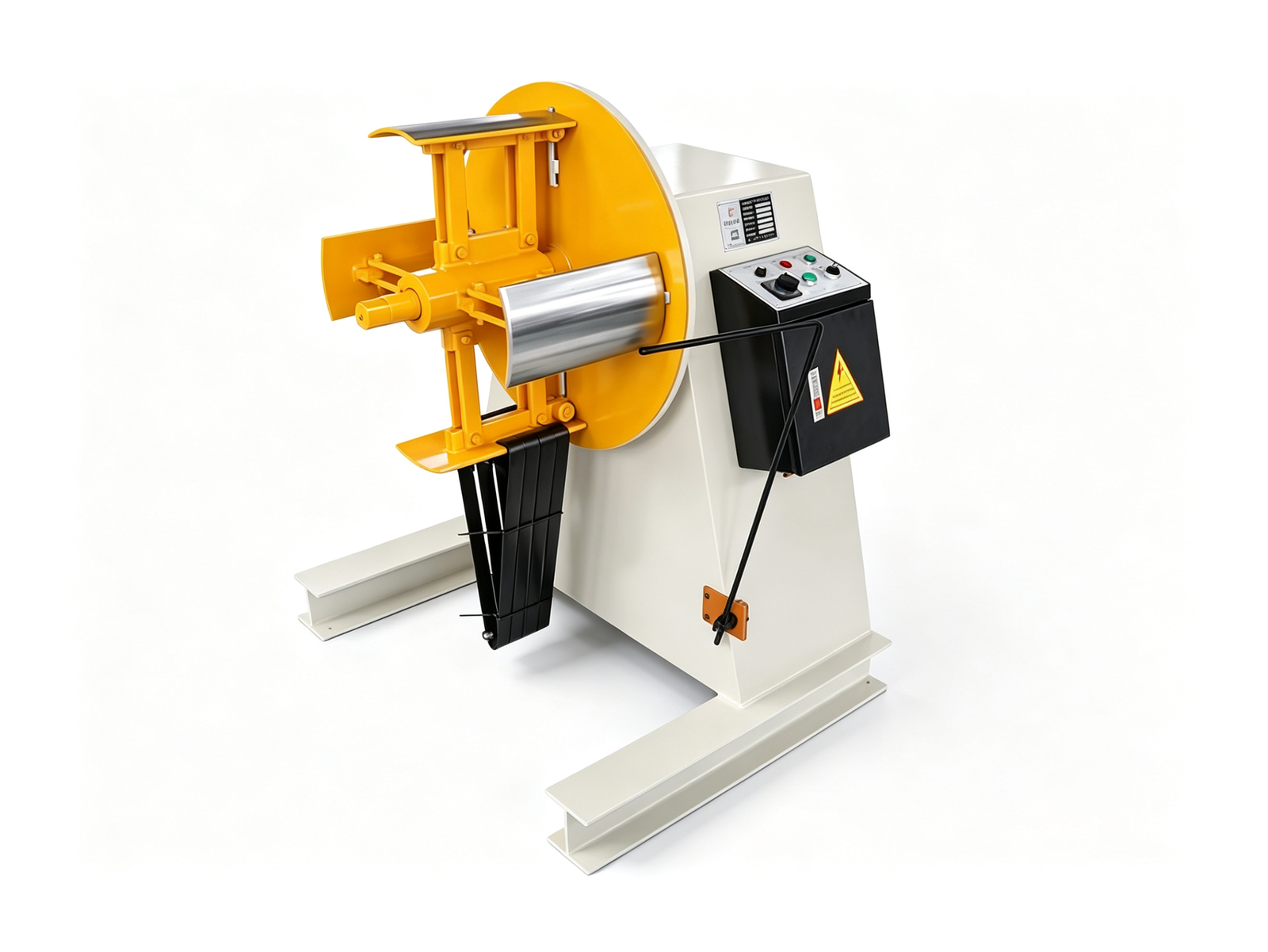
- Decoiler (uncoiler): Holds and unwinds the steel coil. Options include manual, hydraulic, and motorized decoilers with capacities from 1 to 20 tons.
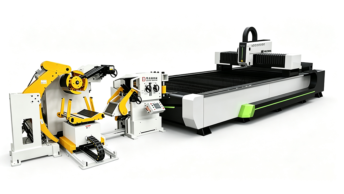
- Straightener / Leveler: Removes coil set (curvature from being wound on a roll). Critical for maintaining flatness and consistent feed accuracy.
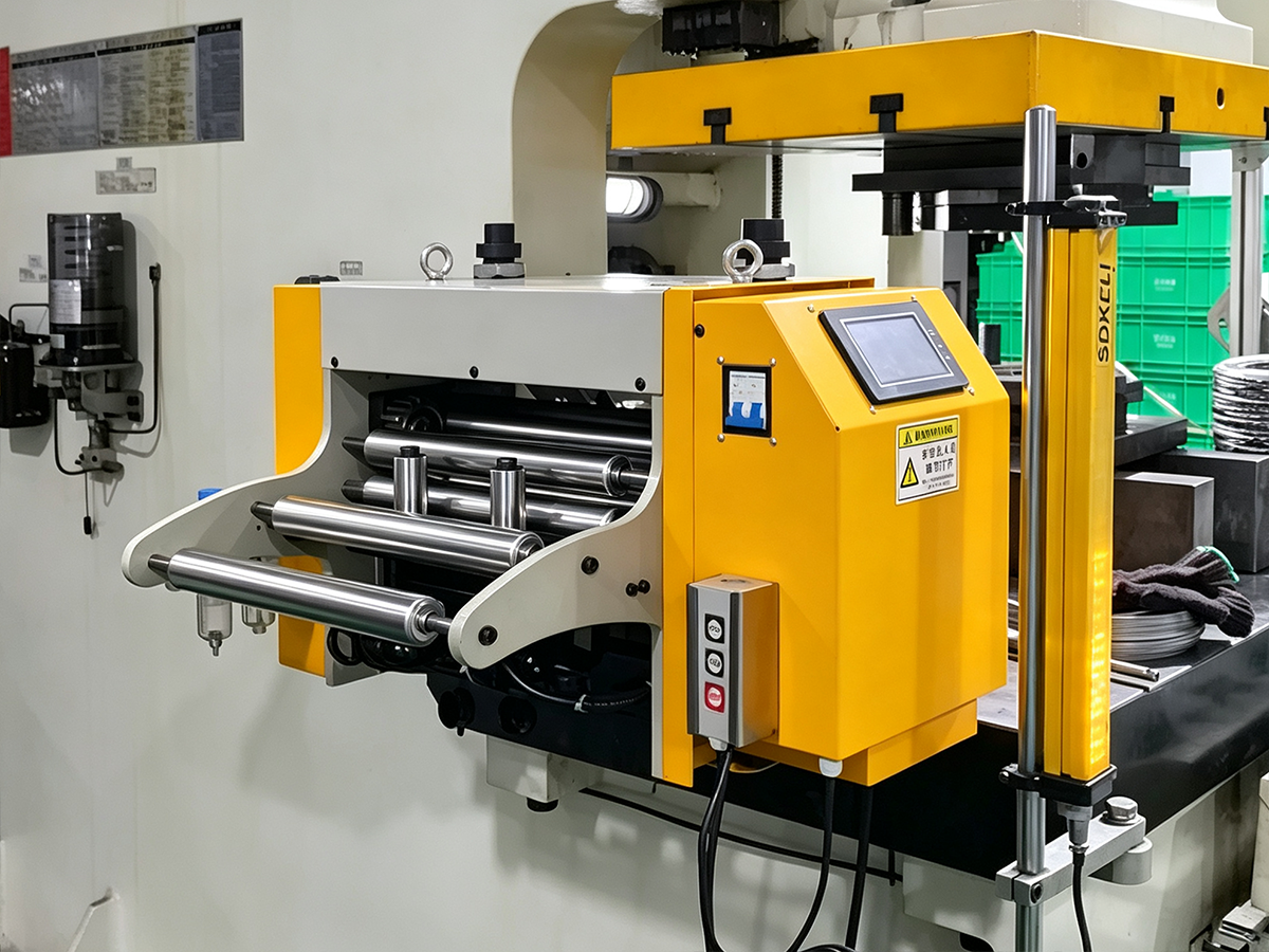
- Feeder: Advances material into the press at the required pitch and speed. Common types: air feeders, roller feeders, and servo feeders (most precise).
Key specification: The feeder must match or exceed the press speed. A servo feeder paired with a 200 SPM press should deliver ±0.05 mm pitch accuracy at full speed.
2. Stamping Press
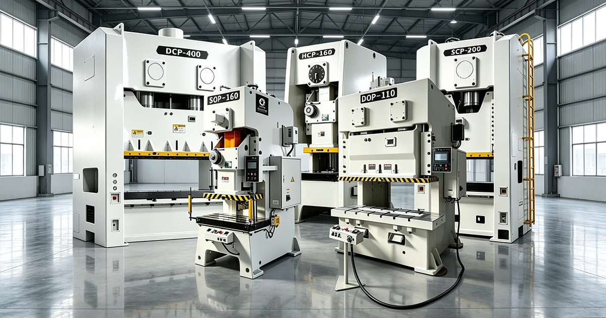
The press is the heart of the line. Selection depends on tonnage, speed, bed size, and accuracy requirements. See our stamping press solutions for detailed guidance on matching press type to application.
| Press Type | Speed Range | Best For |
|---|---|---|
| C-Frame Single Crank | 60–120 SPM | Small to medium parts, general stamping |
| Straight Side Single Crank | 40–150 SPM | Precision parts, progressive dies |
| Straight Side Double Crank | 30–80 SPM | Large parts, wide dies, high tonnage |
| High-Speed Press | 150–400 SPM | Laminations, connectors, high-volume small parts |
| Servo Press | Variable (programmable) | Complex forming, multi-process, energy-efficient |
3. Die System
The die (tooling) defines what the press actually produces. Die types include:
- Single-hit dies: One operation per press stroke. Used in transfer or tandem lines.
- Progressive dies: Multiple stations in one die — each stroke advances the strip through cutting, forming, and bending stations. Ideal for high-volume, complex parts.
- Transfer dies: Parts are moved between stations by a mechanical transfer system. Used for large parts that can't stay on a strip.
Die cost range: ¥30,000–800,000 ($4,000–120,000) depending on complexity, number of stations, and material (carbide vs. tool steel).
4. Part Transfer & Handling
After stamping, parts must be safely removed and transported. Options include:
- Manual take-off: Simple, low cost — for low-volume or large parts.
- Part ejectors / air blowers: Automated part removal from the die area.
- Robot arms / pick-and-place: For automated stacking, sorting, or transfer to secondary operations.
- Conveyor systems: Belt or roller conveyors for continuous part flow downstream.
5. Quality Inspection
In-line inspection catches defects before they accumulate. Common systems:
- Sensor-based monitoring: Detects missing punches, short feeds, and double-thickness material.
- Vision inspection: Camera systems check part dimensions, burrs, and surface defects at full line speed.
- Tonnage monitoring: Load cells on the press detect die wear, material variation, and overload conditions in real time.
Step-by-Step: Setting Up Your Stamping Line
Follow this proven sequence to configure a reliable, efficient production line:
Step 1: Define Your Product Requirements
Before selecting any equipment, gather these critical inputs:
| Input | Why It Matters |
|---|---|
| Part dimensions & geometry | Determines press bed size and tonnage |
| Material type & thickness | Affects die clearance, feed system, and tonnage |
| Production volume (parts/year) | Determines press speed and automation level |
| Tolerance requirements | Sets minimum press accuracy class |
| Surface finish requirements | Influences die material and coating |
| Secondary operations needed | Affects line layout and downstream equipment |
Step 2: Calculate Stamping Tonnage
Accurate tonnage calculation prevents press overload and ensures consistent quality.
Basic formula:
Tonnage (tons) = Cutting Perimeter (mm) × Material Thickness (mm) × Shear Strength (MPa) ÷ 1,000Example: A 200 mm perimeter bracket in 2.0 mm mild steel (shear strength ~300 MPa) → 200 × 2.0 × 300 ÷ 1,000 = 120 tons. Add 20–30% safety margin → select a 150–160 ton press.
Pro tip: Always include forming, drawing, and bending forces in addition to cutting force. For deep drawing, use: Tonnage = π × D × t × T × K (where K is the drawing coefficient, typically 0.5–0.8).
Step 3: Select the Press
Match the press to your tonnage, speed, accuracy, and bed size requirements. Key factors:
- Tonnage: Calculated above, with safety margin.
- Stroke: Must exceed part height + die clearance + strip thickness. Short stroke for flat parts; long stroke for deep draws.
- Bed size (L × R × F × B): Must accommodate the die plus bolsters and feed width.
- Speed (SPM): Match to production volume. Higher SPM = higher output but requires better feeding and die quality.
- Accuracy: JIS Class 1 for general stamping; JIS Special Class for precision parts.
- Rigidity: Straight-side frames resist deflection better than C-frames under off-center loads.
Browse Taifeng's complete product range to find the right press for your application.
Step 4: Configure the Feed System
The feeder is the second most critical component after the press. Match it carefully:
- Feed pitch accuracy: Must be tighter than your part tolerance. Servo feeders achieve ±0.02–0.05 mm.
- Feed speed: Must sustain the press SPM without missing pitches.
- Material width & thickness range: Feeder capacity must cover your coil specifications.
- Leveling capability: Thicker material or high-coil-set stock needs an integrated leveler.
Recommended pairing: Servo feeder + 4-roll leveler for material 0.5–6.0 mm thick; air feeder for simple, low-speed applications under 80 SPM.
Step 5: Design the Line Layout
Efficient layout minimizes material handling and maximizes safety. Key principles:
- Linear flow: Coil → Decoiler → Leveler → Feeder → Press → Part collection. Avoid backtracking.
- Clearance zones: Maintain at least 1 meter clearance around the press for die change and maintenance access.
- Safety barriers: Light curtains, two-hand controls, and physical guards around the press and feed area.
- Die change access: Plan for die change carts, rolling bolsters, or quick-die-change systems if changeovers are frequent.
Step 6: Integrate Automation
Automation transforms a basic stamping line into a high-efficiency production system. Levels of automation:
| Level | Components | Suitable For |
|---|---|---|
| Basic | Manual decoiler + roller feeder + manual take-off | Low volume, large parts, budget lines |
| Semi-auto | Motorized decoiler + servo feeder + air ejector | Medium volume, 60–150 SPM |
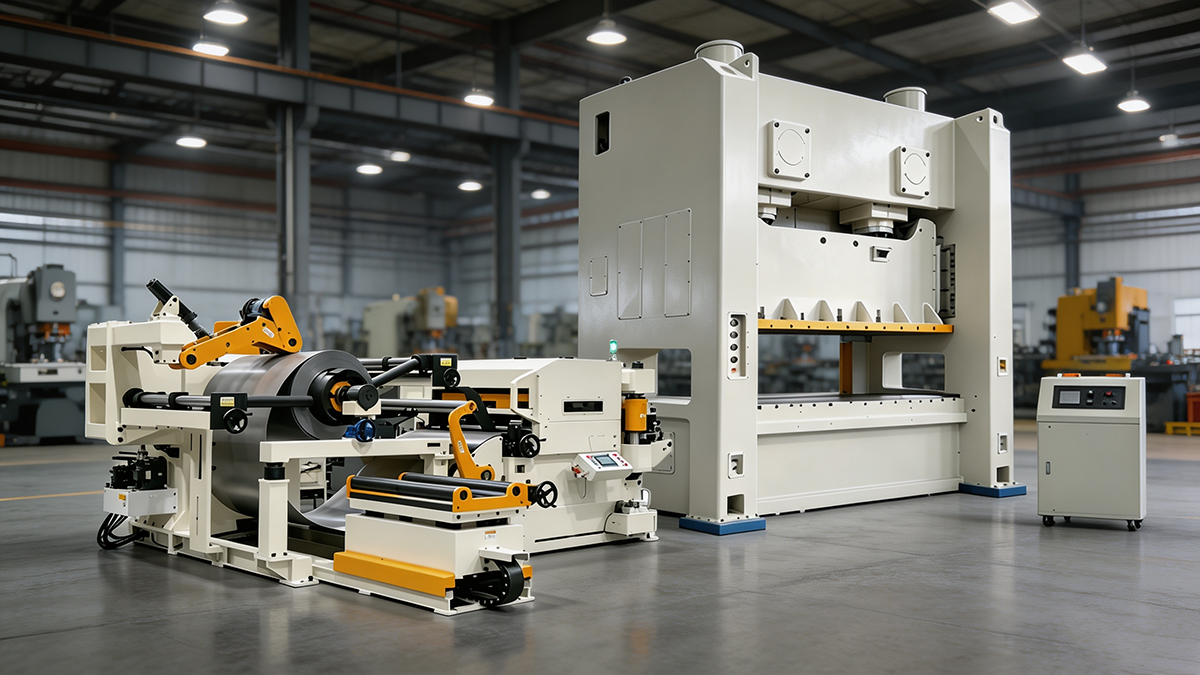
| Full auto | Coil line + servo feeder + press + robot + conveyor + inspection | High volume, 150+ SPM, lights-out production |
| Integrated | Full auto + MES/ERP connectivity + predictive maintenance | Industry 4.0, multi-line factories |
Step 7: Establish Quality Control
Build quality into the line, not just at the end:
- First-article inspection: Measure all critical dimensions on the first 5–10 parts after setup or die change.
- In-process checks: Hourly or per-lot sampling with go/no-go gauges or CMM measurement.
- Die maintenance schedule: Track stroke counts and sharpen/replace punches before quality degrades.
- SPC (Statistical Process Control): Monitor key dimensions with control charts to detect drift early.
Common Mistakes When Setting Up a Stamping Line
- ❌ Undersizing the press: Running near 100% tonnage capacity accelerates wear and risks overload shutdowns. Always maintain 20–30% margin.
- ❌ Mismatched feeder and press speed: A feeder that can't keep up causes misfeeds, short shots, and die damage.
- ❌ Ignoring die change time: Frequent changeovers kill productivity. Invest in quick-change systems (rolling bolsters, die carts) if you run multiple parts.
- ❌ Neglecting coil quality: Inconsistent coil thickness or poor edge condition causes feeding errors and dimensional variation.
- ❌ No tonnage monitoring: Without real-time tonnage data, you won't detect die wear, material changes, or misalignment until parts go out of spec.
- ❌ Poor housekeeping: Scrap buildup in the die area causes double-hits and die damage. Plan for scrap conveyors and regular die area cleaning.
The ROI of Stamping Line Automation
Automation is no longer a luxury — it's a competitive necessity.
- Labor reduction: A fully automated line can run with 1 operator per 2–3 presses vs. 1 operator per press in manual mode.
- Scrap reduction: Automated feeding and inspection reduce scrap rates from 3–5% to under 1%.
- Consistency: Servo feeders and automated handling eliminate human variability in pitch, timing, and part placement.
- Uptime: Modern servo systems with predictive maintenance reduce unplanned downtime by 30–50%.
Typical payback period: 12–24 months for semi-auto upgrades; 18–36 months for full automation, depending on volume and labor cost.
Taifeng Stamping Line Solutions
With nearly 40 years of press manufacturing experience, Taifeng Machinery provides complete stamping production line solutions — from individual presses to fully integrated turnkey lines.
What we offer:
- Full press range: 25–600 tons, C-frame and straight-side, single and double crank
- Servo presses with programmable slide motion for complex forming applications
- Complete coil handling systems: decoilers, levelers, servo feeders
- Turnkey line integration: press + feeder + automation + quality systems
- Die design consultation and progressive die sourcing assistance
- On-site installation, commissioning, and operator training
- 12-month warranty and lifetime technical support
Shipped to: Vietnam, India, Mexico, Turkey, Indonesia, Thailand, Brazil, Egypt, and 30+ countries worldwide.
Ready to set up your metal stamping production line? Contact us with your part drawings, material specs, and production targets — our engineers will design the optimal line configuration and provide a detailed quote within 48 hours.